Introduction
The primary purpose of a confocal microscope is to image deep into the tissues of thick specimens and produce optical sections for 3D reconstruction. This is achieved by the elimination of out-of-focus glare from the detector via the use of pinholes.
When fluorescent specimens are imaged using a conventional widefield microscope, fluorescence emitted by the specimen that appears outside the focal plane can interfere with the resolution of those features that are in focus, leading to blurred images. This is especially the case for tissues that have a thickness of greater than 2 μm. In the confocal approach, the use of a detection-side pinhole that is in the same conjugate focal plane as the point of illumination prevents secondary fluorescence originating from below or above the focal plane from reaching the detector.
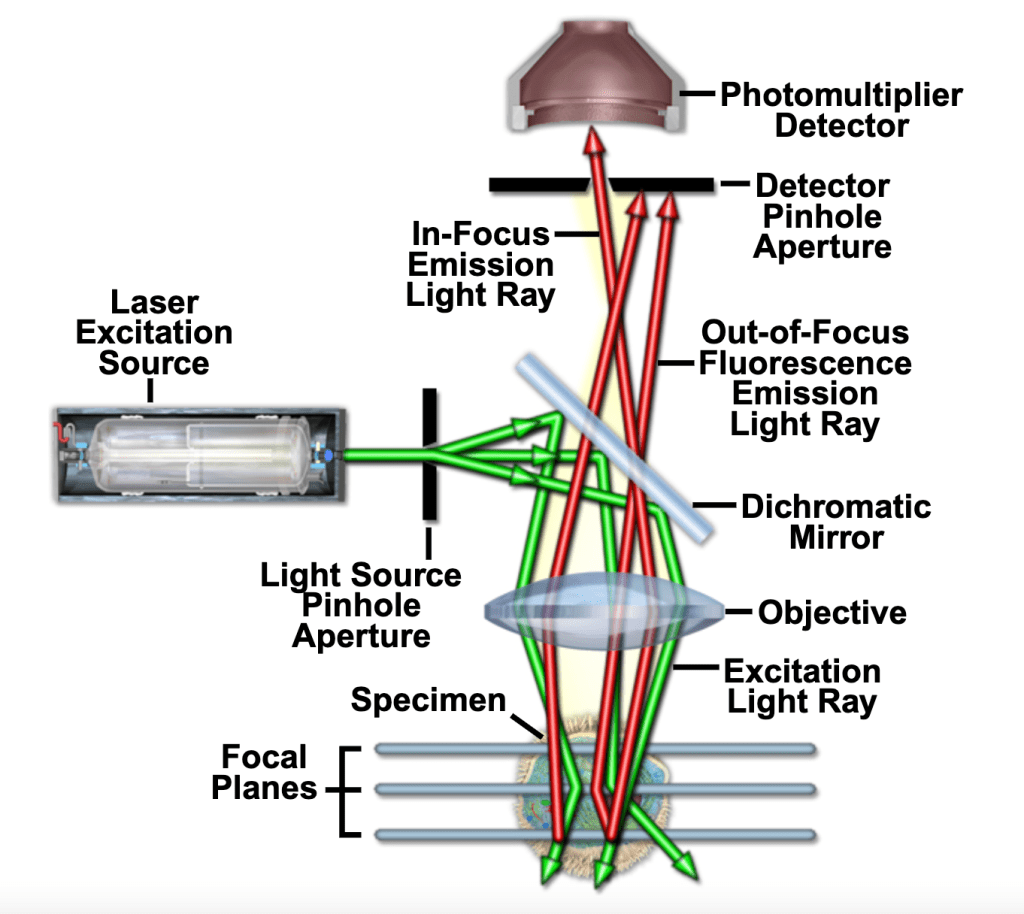
The basic components of a modern confocal microscope are the pinhole, the objective lens, and low-noise detectors. A confocal microscope also typically includes fast scanning mirrors, filters for wavelength selection, and laser illumination. The principal light pathways of a confocal microscope are shown below. In fig. 1, light from a laser source passes through a dichromatic (i.e., dichroic) mirror and is reflected to the objective, which focuses the beam on a point in the sample. Emitted light passes back through the objective lens, the dichromatic mirror, and is detected by the photomultiplier detector (PMT). The detection-side pinhole works to prevent out-of-focus glare from reaching the detector. Varying the size of the pinhole alters the amount of light collected and the thickness of optical sections.
The confocal approach provides marginal improvements in axial and lateral resolution when compared to widefield microscopy. The best resolution in confocal microscopy is ~0.2 μm laterally (i.e., in the xy-plane) and ~0.6 μm axially (along the z-axis), and may be achieved when the pinhole is closed to the minimum size. The resolution possible in confocal microscopy is somewhat better than that in widefield microscopy, yet still considerably less than that of transmission electron microscopy.
Pinhole and its effects
When light passes through an aperture of any size, diffraction occurs. Even for perfectly designed optics, the image of a point source will be blurry due to diffraction. The smallest shape that can be generated is the image of a spot-shaped light and is called a “point spread function” (PSF). The PSF is formally defined as the distribution of light in the focus of an optical device when imaging a dimensionless spot (see fig. 2). The central spot in this pattern is called an “Airy disc.” The size of the Airy disc is a function of the wavelength, the numerical aperture (NA), the magnification of the objective lens, and the magnification of internal optics of the microscope.

In the confocal approach, the illumination source is projected on a pinhole which acts as a spot-shaped source. The emission light is similarly fed through a detection-side pinhole before recorded by a sensing element. In this way, both illumination and detection are focused to the same spot (i.e., the two points are “confocal”). For general confocal imaging, the detection-side pinhole should just pass the Airy disc. The diameter in this case is designated as one Airy Unit (1 AU). Since the size of the Airy disc is not constant, the required pinhole diameter is different for different colors and for distinct objective lenses.
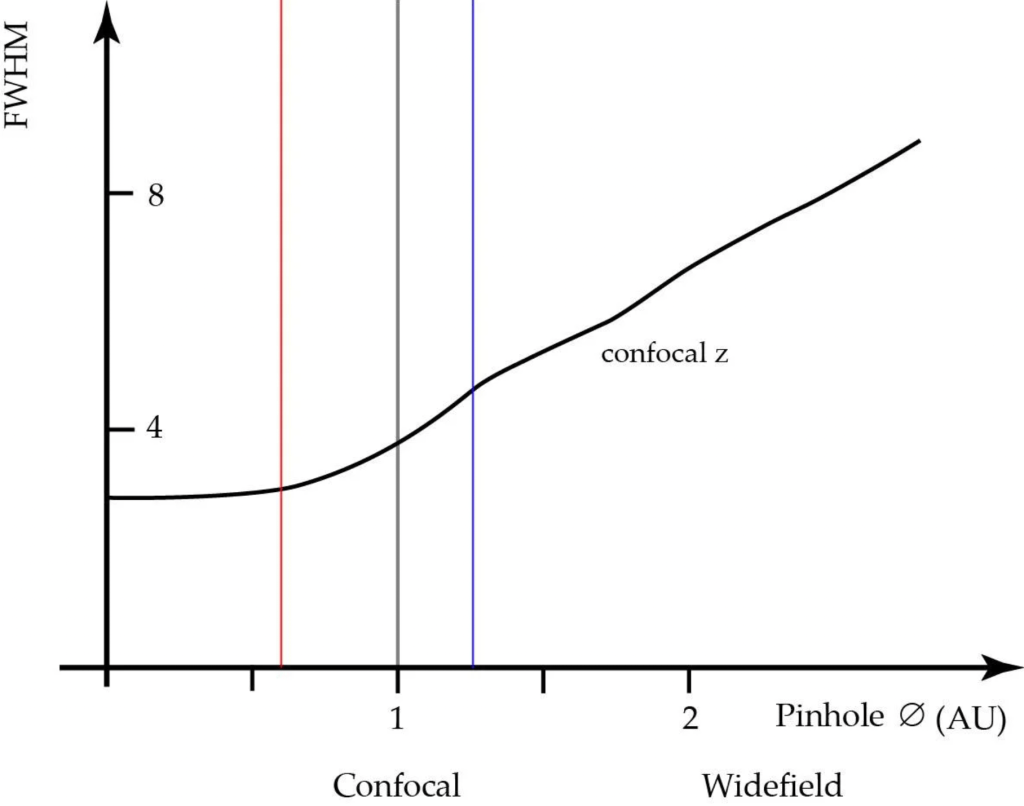
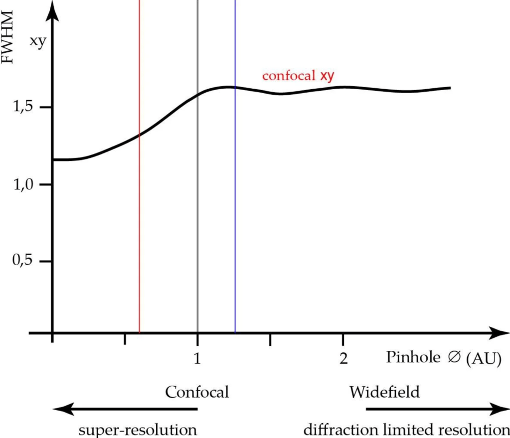
The pinhole diameter affects both axial and lateral resolution (see fig. 3 and fig. 4). The axial resolution can be improved by closing the detection-side pinhole to smaller than 1 AU, but at the cost of signal to noise ratio (SNR). The best axial resolution is obtained when the pinhole diameter is at zero, but practically speaking, the thickness of the optical section at the diffraction limit is only about 25% better than at 1 AU. Moreover, at pinhole zero, lateral resolution improves by around 30%.
If pinhole size increases beyond 1 AU, more and more extrafocal glare will reach the sensing element and start to blur the sharp focal signal. There is an apparent increase in contrast (SNR) due to the collection of light from outside the focal plane. As the pinhole approaches infinity, the microscope behaves like a conventional widefield microscope.
Types of confocal microscopes
Confocal microscopes can be classified by the means by which the illumination beam is scanned across the specimen. In stage scanning confocal microscopes, the illumination beam is kept stationary and the specimen itself moves on a vibrating stage. However, this scanning method can cause wobble and distortion in biological samples, is slower compared to scanning the beam, and requires a high degree of mechanical precision for optimal resolution.
For these reasons, most modern confocal microscopes scan the illumination beam across a stationary specimen. Two different kinds of beam scanning technologies are typically used: single-beam scanning and multiple-beam scanning. In a laser scanning confocal microscope (LSCM), the most common type of single-beam scanning technology, a single laser beam is swept over the sample through computer-controlled galvanometer mirrors at the rate of one frame per second. Scanning at near video frame rates can be achieved via acousto-optical devices or oscillating mirrors.
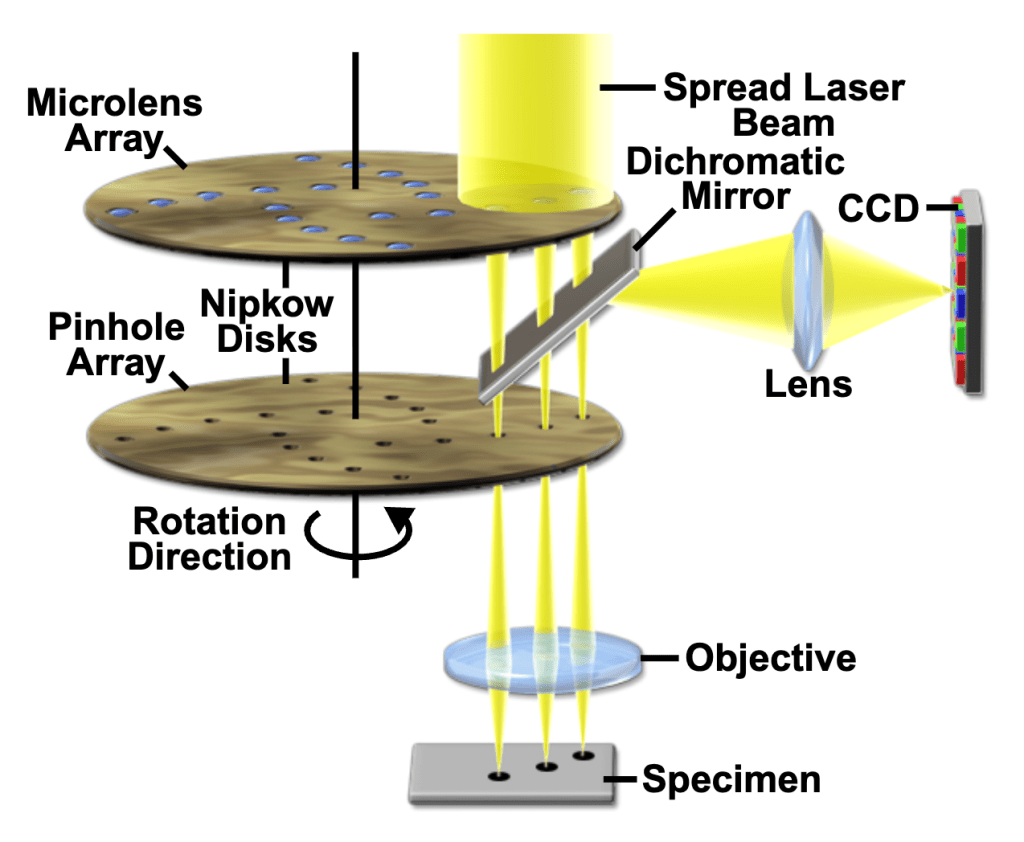
Spinning disk confocal microscopes use some form of Nipkow disks to scan multiple beams at near real time. The Nipkow disk, conceived by German engineer Paul Nipkow (1860-1940) in the 1880s, is a metal disk with ~1% of the surface consisting of fixed-width holes arranged in outwardly spiraling tracks. In systems that employ Nipkow disks, the entire field can be covered at a higher rate. The image is captured with a camera (e.g., CCD) instead of a PMT (see fig. 5).
Aberrations in confocal microscopy
Simply put, optical aberrations cause the images produced by an optical system to not be a faithful representation of the specimen being imaged. In confocal microscopy, there are two major types of aberrations: chromatic and spherical aberration.
Ideally, an objective lens would focus all wavelengths of light to a single point. In reality, all objectives have chromatic aberration, a property whereby different colors of light are focused to different points. In lateral chromatic aberration, horizontal displacements in the image plane cause different colors of light to be magnified differently. This issue can be resolved by restricting the analysis to the center of the image field.
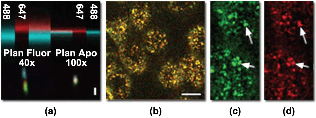
In contrast, axial chromatic aberration, or vertical displacements along the optical axis, is present throughout the microscope field (see fig. 6). The effects of axial chromatic aberration could be minimized in two ways. The first is to sum the entire vertical series of the image volume into a single projection, which circumvents the discrepancy in focal plane but at the cost of losing all vertical information. The second solution is to measure the axial offset of different colors and combine images from different focal planes.
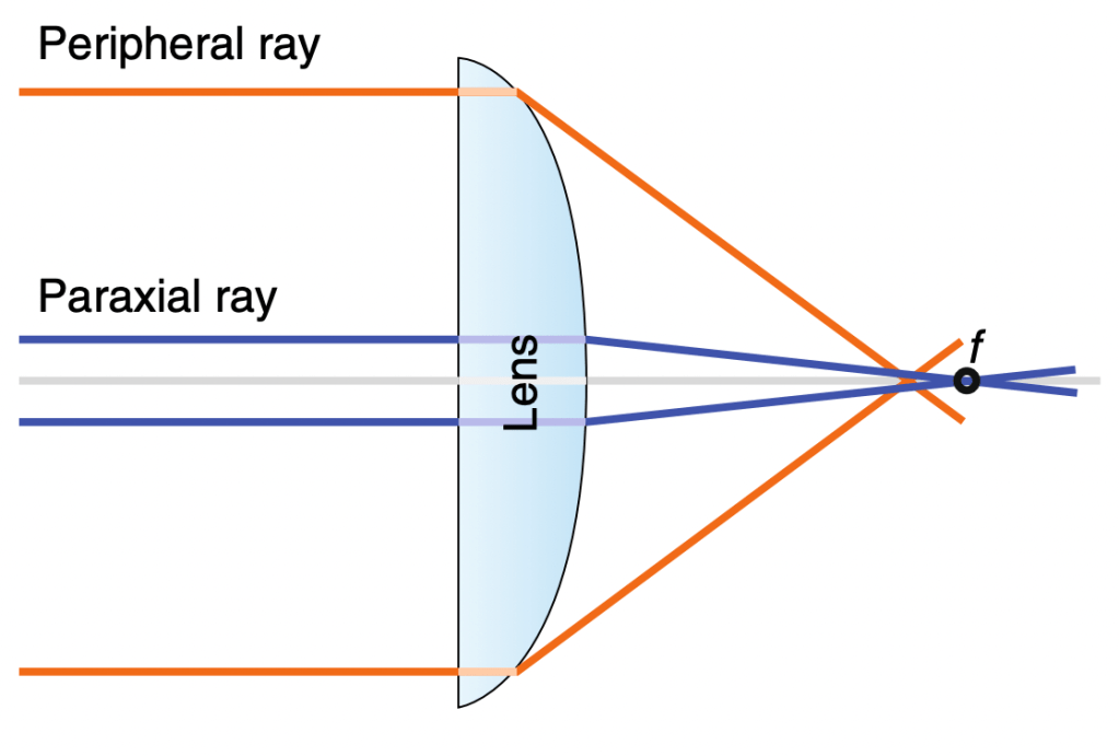
Spherical aberration is a property by which light entering the periphery of a lens is focused to a different point on the optical axis than paraxial light rays that enter near the lens’s center (see fig. 7). A spherically aberrated lens severely decreases the signal in confocal microscopy. Spherical aberration can also be induced by a mismatch between immersion and sample media, worsening axial resolution and can even eliminate fluorescence detection entirely. For instance, spherical aberration can occur when one images a watery cell sample with an oil immersion objective.
References
Borlinghaus, Rolf. “Pinhole Effect in Confocal Microscopes.” Leica Microsystems, 2017.
Diel, Erin, et al. “Tutorial: Avoiding and Correcting Sample-Induced Spherical Aberration Artifacts in 3D Fluorescence Microscopy.” Nature Protocols, 2020.
Dunn, Kenneth and Exing Wang. “Aberrations in Confocal Microscopy.” Nikon MicroscopyU.
Elliott, Amicia. “Confocal Microscopy: Principles and Modern Practices.” Current Protocols in Cytometry, 2020.
Paddock, Stephen, et al. “Introductory Confocal Concepts.” Nikon MicroscopyU.
